Principle of Induction Lighting
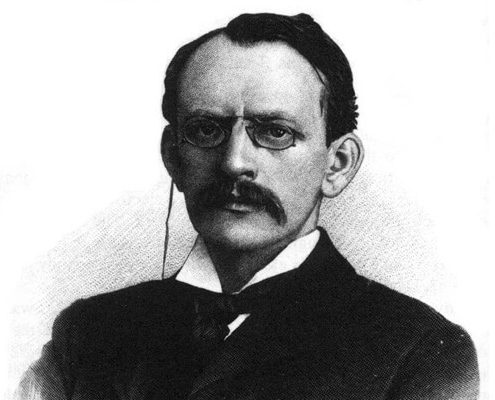
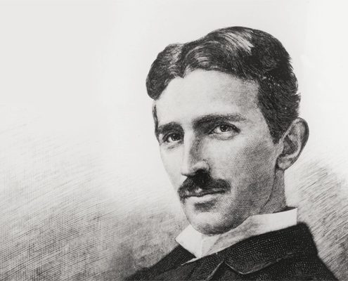
The induction lighting was first discovered by Hittorf in 1880s, and more further observations were made soon after by J.J.Thomson. The first actual induction lamp was shown by Tesla in 1890s. Because of Tesla’s special contribution, the induction lighting is also called as Tesla bulb by people.
The induction lamp is fundamentally different from the traditional one, which employs electrodes as electron source. The operation frequency of electrodeless discharge lamp is usually in the range of hundreds of KHz to tens of MHz. The lighting should be on a special generator to provide high frequency power. Without electrodes, the energy coupling coils are needed for the energy coupling into the plasma. Super long lifespan and perfect lumen maintenance would be achieved with this special kind of electromagnetic lamps.
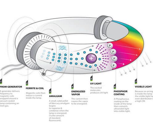
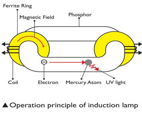
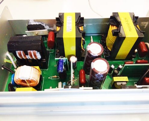
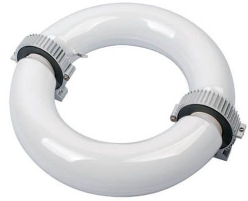
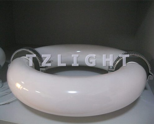
The induction lamp is consisting of three main parts, the high frequency generator (always called electronic ballast or driver), magnetic coils and the induction tube. The electronic ballast is to generate high frequency current 230 KHz at rated power. When the high frequency current flows through the magnetic coils wrapping around the ferrite cores, inductive electric field is produced to maintain the gas discharging. The mercury vapor emits UV light which strikes the phosphor and makes the bulb light. The two magnetic coils are in parallel with each other, the turns of the coils’ wires are determined by the different specifications demands. Discharge gas is consisting of mercury gas with noble gas like Ar and Kr. The pressure of Mercury is controlled by the amalgam. Several assistant amalgams are posited close to the magnetic core to help quick operation of induction lamps. Above is the simple principle of how does induction lighting works.
The process of energy transferring from the magnetic coil to the discharge plasma can be considered as a model of a transformer. The magnetic coil is equivalent to the primary winding and the magnetic lamp bulb is equivalent to the secondary winding. The inductively coupled discharge is maintained by high frequency voltage built in the induction bulb.
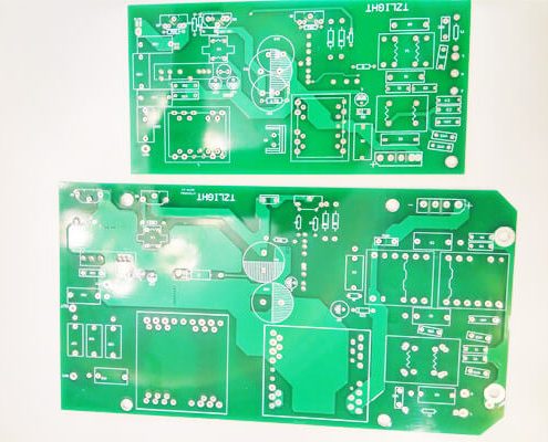
The high frequency generator (always called electronic ballast or driver) is made of four main parts. First is an EMI filter to reduce harmonics from the supply of alternating current. The second part is a bridge rectifier, this converts AC to DC power. After that is the PFC circuit which boosts the DC voltage to a constant 400V value and increases the power factor to 0.95+ efficiency.The last part of the ballast is an inverter which converts the DC power to high frequency AC.
The highlight of this ballast is the application of IC chip controlled improving the performance of the total system. The inverter is controlled by the IC chip providing driving signals controlling the frequency. Since the lamp power is inversely proportional to the operation frequency when the voltage is constant, lamp power changes with the changes of operation frequency so that the dimming could be achieved. With controls, 30%~100% dimming range can be achieved without negative effects on the lamp. PFC is controlled by IC chip which guarantees the induction lamp to work properly from wide voltage range with PFC than 0.95. This advantage benefits the application of high rate of fluctuation of power supply.
Generally, the induction lighting technology is an old but new applications today with a lot of updated new technology like IC controlling and high lighting efficiency. The connection of old and new remakes the new life of induction lighting.

